Available
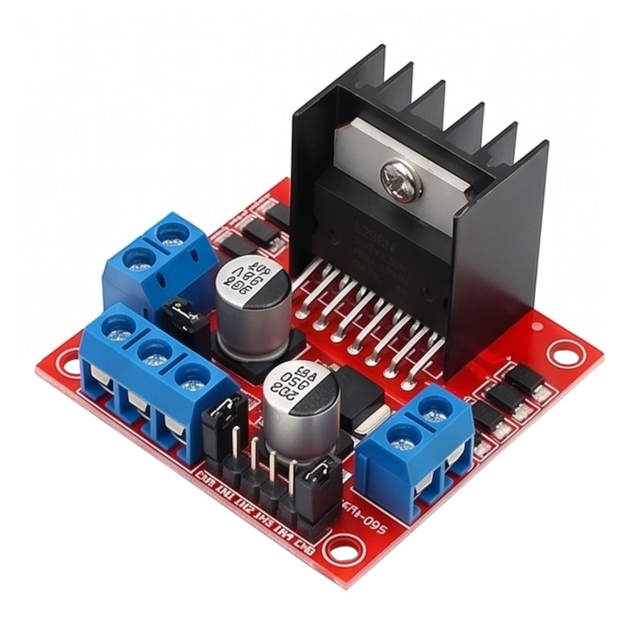
L298N Module Red Board (Dual H-Bridge Motor Driver Using L298N)
75.00 EGP
A high-performance power module based on the L298N Dual H-Bridge Driver chip. It is used for the overall control of the speed and direction of rotation of two independent DC motors, or a single bipolar stepper motor, using low-voltage control signals from a microcontroller (such as an Arduino, ESP32, or Raspberry Pi). Technical Specifications: Driver Chip: L298N Dual Full-Bridge Driver IC. Motor Operating Voltage ($V_S$): 5V to 35V DC. Maximum DC Current per Channel: 2A (Maximum Peak Current up to 3A per channel). Maximum Operating Power: 25W. Onboard 5V Regulator: Provides a 5V supply to the control circuit or microcontroller board when the module is supplied with motor voltages between 7V and 12V. Aluminum Heatsink: Integrated for chip cooling and heat dissipation under high loads. Diode Protection: The board contains integrated protection diodes to minimize electrical interference and reverse voltage. Back EMF generated by the motors. Pinout and Interfaces: Power and Motor Terminal Block (Screw Terminals): +12V/VMS: External power input for the motors (5V-35V). GND: Common ground (must be connected to the microcontroller's ground). +5V: 5V output (when the regulator is activated) or input for the control logic (when the regulator is deactivated). OUT1 & OUT2: Connecting pins for the first motor (Motor A). OUT3 & OUT4: Connecting pins for the second motor (Motor B). Logic Pins: IN1 & IN2: Control the direction of rotation of the first motor (Motor A). IN3 & IN4: Control the direction of rotation of the second motor (Motor B). ENA & ENB: Drive activation pins; remove the jumper and connect them to the PWM pins on the microcontroller to control the motor speed.
Category:
متحكمات وأجهزة
Share:
Similar Products
Related Products